Wednesday, June 17, 2009

Day 27: Preparing for a lift

Today we prepared the walls for the first grout lift. Grout fills the interconnected horizontal and vertical network of cells inside the APEX blocks creating the building structure once the concrete is cured. A lift is the height the grout will be poured at one time. In this case, the lift is 5 courses (approximately 80 ionches). The grout is a thin concrete mix and can leak out through holes and gaps in the walls and bucks. The grout applies hydrostatic pressure on the walls and bucks. This pressure increases towards the bottom of the wall just as water pressure against your body increases the deeper you dive. Corners and thin areas of APEX block are most vulnerable to a phenomenon called blowout – when the grout fractures a portion of the wall material and begins gushing from the opening. We want to do everything we can to avoid blowouts. Some of the things that were completed today:
  • Plumbing vents and drains that penetrated partially into APEX grout cells were surrounded with foam, sealed and supported so that grout would not leak and the plumbing would be accessible in the future.
  • Small wooden forms were installed to properly locate 2 beam support brackets that must be cast into the grout during this lift.
  • Threaded rods were cut and placed into the window and door buck holes drilled yesterday.
  • Walls were shored up after ensuring they were vertical.
  • Made a final check to ensure window and door bucks were level and located properly in the openings.
  • All 6 exterior corners were shored up with a frame after ensuring that the walls were vertical.
  • Holes were drilled through the exterior 2 inch thick skin of APEX block under window openings to provide access for the concrete pump hose. All wall cells will be filled from the top of the 5th course of block, but these additional holes will ensure that grout is placed under the window openings.
  • Gaps around door and window openings and any gaps in the APEX block wall larger than about ¼ inch were filled with closed cell spray foam insulation. This material expands several times its size after being sprayed from the canister and fills the gap to prevent grout leaks.
Following are a couple pics from the end of day 27.


Thanks for reading. I appreciate your comments.

Tuesday, June 16, 2009

Day 26: Even more people, more window bucks, and more courses, oh my!

Justin and Rafael joined the others on the job site today. Here’s what happened:
  • The last window buck in the 1st floor was installed.
  • The 4th and 5th courses of APEX block were completely installed all the way around the home, including the utility room.
  • All vertical rebars were installed.
  • Holes were cut in the window and door bucks through which threaded fasteners will attach the bucks to the APEX block walls.
Here is a pic from the east at the end of day 26.


Stella Status:
Whenever Justin is on the job site, Stella is too. I caught Stella taking a nap in the afternoon. She is about 3 inches longer than the last time I saw her.

Thanks for reading. Feel free to leave a comment.

Monday, June 15, 2009

Day 25: More people, more window bucks, more courses, oh my!

Two new folks started working on the project today: Marty and Joshua - my good friend and neighbor. Here’s what happened:
  • All window and door bucks on the 1st floor were built, and all but one were installed. It is exciting to see the window views appear.
  • The 3rd course of APEX block was installed all the way around the home, and part way around the utility room.
  • The concrete slab was rinsed one last time. Protective material was placed over the slab. Vapor barrier film was placed over the great room floor, and a lightweight cardboard material was placed over the bedroom, bathroom and closet floors. It is expected that these 2 different materials will create different finish stain patterns in the concrete. It will be interesting to see the results later. Here is a pic from the east at the end of day 25.
Thanks for reading. Leave a comment if you like.

Saturday, June 13, 2009

Day 24: Window Bucks

Today we built wooden bucks for the 3 sliding glass doors on the south wall. Bucks provide a mounting surface for the doors and help strengthen the large openings in the APEX block wall. The APEX material has very little strength and will not hold a fastener without additional support. We also stacked up 4 more courses of block to the east and west of the center door. Here is a pic from the southeast at the end of day 24. Thanks for reading. I appreciate your comments.

Thursday, June 11, 2009

Day 23: Cleanup, control joints and more

Today was a welcome low key day after the pour. We removed all of the wooden forms around the home. We began to lay a 3rd course of APEX block. We also began building a door buck with the 3X8 pressure treated wood delivered last week.

Cesar from Diamond D Concrete arrived to cut control joints in the slab. These joints are about 1/8 inch wide and 1 inch deep and should be the first locations where shrinkage and settling cracks occur. The idea is that the crack is hidden at the bottom of the joint and runs straight instead of randomly across the slab. I chose where I wanted the joints located. Cesar snapped chalk lines to identify where to cut. Some joints will be hidden under interior walls and cabinets, and some will be exposed. The joints are usually filled with grout and can become a decorative and defining feature of the floor pattern. Cesar used a SOFF CUT saw to cut the long joints as shown in the pic below.

Then he used a hand held saw to cut joints in areas that were difficult to access – see vid below.


Finally, Cesar rinsed the slab to wash off the concrete dust produced during the cutting process. Here is a pic of the joints near the center of the family room.

For the next several days I will sprinkle water on the slab. This helps slow down the concrete drying process resulting in a stronger slab. Here is a pic of the wet slab from the East at the end of Day 23.

Green comment for today:
When cleaning up on the job site, sort out all recyclable and compostable materials. Try to think of another purpose for materials that would be sent to a landfill. We say we are throwing things away, but there really is no such thing as “away”.

Thanks for reading. Feel free to leave a comment

Wednesday, June 10, 2009

Day 22: Pouring the concrete slab

I worked late yesterday (Tuesday) preparing for the slab pour, so I did not post. Some of the tasks completed Tuesday were:
  • Completed routing of the remaining 4 PEX heating circuits.
  • Pressurized the PEX heating tubing to 70 psi to identify a failure if one occurs before or during the pour
  • Built wooden supports for the corners and window openings to prevent them from distorting outward when the concrete is poured
  • Built a variety of wooden forms to create 1) a concrete curb detail around the shower, 2) notches in the door openings for the doors to seat into and 3) a depression for a tile mosaic art piece in front of the sliding glass door
  • Photographed, measured and sketched all conduits and tubes that are under locations where fasteners may be anchored into the slab, i.e. interior walls and kitchen cabinets.
Here is a picture from the end of Tuesday.

On Wednesday, the slab was poured. The folks from Diamond D Concrete, Las Animas Concrete and Pacific Coast Concrete Pumping showed up early. Diamond D used a laser level to create a line around the inside of the home that represented the finish height of the slab. I am going to let pics and vids do most of the talking. In the following vid you can see concrete being pumped in the foreground and application of a rough screed in the background.


A perforated roller screed is then used to push down the larger aggregate and leave smooth textured concrete on top (called cream).


The cream surface is then finish screed by hand.


The surface is then rough troweled by hand.

A power screed is then run over the surface.


The guys then worked the surface further twice more with hand trowels to get the finish I desired – not too rough and not too smooth…just right. The guys really did a great job! All of the hard work and preparation from the past several weeks paid off. The day went by with few troubles. I’ll close with a pic from the East at the end of the day.

Green comment for today:
Consider concrete as your finished floor. Less material is required to stain the concrete than to cover it with carpeting or wood. The results of stained finish floors are limited only by your imagination - check out Diamond D's gallery.

Thanks for reading. Feel free to leave a comment.

Monday, June 8, 2009

Day 20: Water, water everywhere

It was an all-plumbing Monday. Coady, Adam and Erik showed up to run all the water supply plumbing that will be cast into the concrete slab. The main drinking water supply was run into the utility room, and all of the fixtures were supplied with hot and cold water lines (sinks, washer, showers). The pic below shows the larger white supply line entering the utility room from the bottom. The blue utility sink and washer hot and cold lines can be seen on the far wall. Once all of these lines were positioned, they were capped off and the entire system was pressurized with water at 90 psi. Pressurization ensures that any damage before or during pouring of the slab can be identified and repaired.

The other plumbing task started today was routing of tubing for the underfloor hydronic heating system. For this system, PEX tubes carry warm water pumped from a storage tank into the concrete slab to heat the home. The PEX tubing is supplied on 1000 foot rolls. A device called a decoiler (see pic below) makes unspooling the PEX simpler than I had imagined.

My floor has 6 PEX tubes - called circuits - each about 175 feet long. They all start and end at the utility room. In between they run back and forth and are spaced apart appropriately to deliver uniform heat into the slab. The runs are spaced closer together near exterior walls where heat loss from the slab is greatest. The coils are spaced further apart near the center of the home where heat loss from the slab is least. The tubes are also routed to avoid being under cabinets and the refrigerator where heating is not required. The following pic shows some of the white PEX runs in the kitchen.The PEX tubing is fastened to the top of the rebar so it does not move during the concrete slab pour. Two of the 6 circuits were completed today.

Green comment for today:
Consider some form of radiant heating for your home. The advantages over a forced air heating system are:
  • Greater energy efficiency because the warmth is supplied closer to where we humans want it - near our bodies. Hot air from a forced air system quickly rises to the ceiling and forces the system to turn on more often to maintain the same comfort level as a radiant heating system.
  • The system is quiet.
  • It is the most comfortable form of heat. We humans would rather be kept warm with radiant heat than warm air.
  • There are no fans blowing dust around the home.
Thanks for reading. I enjoy your comments.

Saturday, June 6, 2009

Day 19: Electrical preparations and more rebar

Today we completed routing all of the electrical and Cat5 conduits that will be cast into the concrete slab - see pic below. I like having the Cat5 cables in conduits. If technology for wired data in the home changes in the future, I just need to pull new wires through the conduits.

Victor and Fernando from Monterey Bay Rebar were back today to place the concrete slab rebar. Once again, they made the job look easy and finished quickly - see pic below. Three inch thick dobies were placed on the sand to support the rebar approximately at mid height of the 6" thick slab.

Thanks for reading. Please leave a comment if you like.

Thursday, June 4, 2009

Day 18: Ready for pro beach vollyball

Today we placed the remainder of the Insul-Tarp and spread approximately 2” of sand over the top. The inside of the house looked like a beach at the end of the day – see pic below. It spread much more easily than the gravel.

The use of sand is questioned given results of the "sand under concrete slab" search I did. Nonetheless, it is required per California Building Code.

Some other tasks completed today:
  • The remainder of gravel was spread in the utility room.
  • A vapor barrier was placed over the gravel in the utility room. Insulation is not required because the room is not heated.
  • Sand was placed over the vapor barrier in the utility room.
  • 5 inch diameter joles were drilled at the top of the 1st course of APEX block at every other vertical core where a rebar will connect to the concrete slab – see pic above.
  • Big Creek Lumber dropped off the window buck material – see vid below. The window bucks for my home are pressure treated 3X8 douglas fir beams that will frame the window and door openings. They provide a stable surface to attach the windows and doors.


Green comment for today:
When designing a home in a winter heating season climate, place the majority of properly shaded window surface area on the south wall in the northern hemisphere, and on the north wall in the southern hemisphere. This will take advantage of free winter heat from the sun. This is one of the fundamental concepts of Passive Solar Design. Start with a value of 50% to 75% of your total window area. Then use a building energy analysis tool like HEED to compare designs with more and less window area with your starting point. You will find a percentage that provides the lowest heating energy need annually. This percentage is the most thermally efficient for your home. There may be reasons other than energy efficiency to increase or decrease the window surface area, but at least you will have a starting point to deviate from.

Thanks for reading. Please leave a comment if you like.

Wednesday, June 3, 2009

Day 17: The gravel spreading is complete and insulation

Gravel spreading was completed in the main home today thanks to Trevor. Only the utility room remains undone, but it is small. After a bit of cleanup, a product called Insul-Tarp was rolled out over the gravel – see pic below.

With a concrete slab floor, the following items should be addressed:
  1. Heat leaking out of the home through the floor
  2. Moisture vapor entering the home from under the floor
Insul-tarp addresses both concerns. I was convinced of the insulation characteristics as soon as I knelt down on the surface to tape the seams. I immediately felt about 10 degrees warmer from the heat reflecting off the surface. I am convinced the product will help make my home more energy efficient.

Here is a pic from the West showing the Insul-Tarp installed over half of the floor.

Green comment for today:
Insulate under a concrete slab floor to reduce heat loss. Energy use will be lower, and the blue marble will be a little happier.

Thanks for reading. Feel free to leave a comment.

Day 16: June rain...

There was no post on Tuesday evening because I needed to prepare for rain. The action was more of the same as Monday. A 2nd course of blocks was added and shimmed. In the pic below you can see three gaps in the 2nd coursw on the long wall to the left. These are the approximate locations for the South sliding patio doors. It is exciting to see the home taking shape.

See that pile of sand off to the left? It means more hard labor coming soon. Fortunately, it is much easier than spreading gravel.

Thanks for reading. I appreciate your comments.

Monday, June 1, 2009

Day 15: Shimming blocks

There is not much new to see today. We spent the entire day adding shims underneath the first course of blocks to make their top surfaces level. This is a time consuming but very important step on the first course. Once we are complete, the remaining courses will go up faster.

A couple other things happened today:
  • Coady the plumber stopped by to pack some fine soil around the plumbing pipes positioned within the gravel layer. The soil prevents abrasion from the gravel.
  • Erik Dazey, the electrician, stopped by to begin laying out the plastic electrical conduit that will carry electric utility power into the utility room, as well as some smaller conduits that will be positioned under the concrete slab to carry wires from the distribution board to outlets and appliances in the home.
Green comment for today:
Try to locate and use materials on the job site if possible. It minimizes manufacturing of new materials. Two examples from today:
  1. Rather than purchasing sand, Coady spent some time sorting out fine soil from the recent excavation for use in protecting the plumbing.
  2. Trevor used a piece of scrap wood I found over the weekend to cut some shims rather than using new shims.
Cindy and I spent last weekend together on site. She helped with some hard labor. While I cut a few small footings, she moved some gravel. Here is a pic of her in action. I've never seen such a big smile on someone schlepping gravel.


Thanks for reading. Feel free to post a comment if you like.

Saturday, May 30, 2009

Day 14: Spreading gravel and laying out the first course of block

We started spreading the pile of gravel today. There is no maneuvering room for heavy equipment inside the walls, and a gravel pump does not exist, so we moved it by hand. We first placed some gravel around the pipes close to ground level. Then we loaded the wheelbarrow and moved little piles around the subgrade. It was harder work than moving APEX block the day before. My appetite has increased.

We also started laying out the 1st course of APEX block. This was fun and challenging. It is rewarding to see the blocks fit well over the rebar and have dimensions match what is on the plans. The corners present little puzzles. My walls are not an exact number of blocks long, so the last block must be trimmed to fit. Horizontal L shaped corner rebar must be placed. We will probably try several different methods before we come up with a solution that works best.

Here is a pic of the site from the East.

Green comment for today:
Consider manual labor now and then. It does take more time, but it has some advantages:
  • It’s quiet, so you can and hear the tunes playing on the solar powered radio. If you are working with someone else, you can have a conversation.
  • It saves fuel.
  • It’s great exercise... if you don’t throw out your back.
Thanks for reading. Post a comment if you like.

Thursday, May 28, 2009

Day 13: APEX blocks arrive, and more Plumbing

Correction from the plumber:

The reason the ABS pipe is wrapped in foam when in concrete is to allow expansion and contraction of the pipes so they don't wear and fracture over the years. Thanks Coady!

===========================================================

The APEX wall building blocks arrived today. The road I live on is not wide enough at my driveway to provide access for the large delivery truck. For this reason, the material was moved off the delivery truck to a smaller flatbed for shuttling about 1.5 miles to the job site. A forklift removed pallets from the delivery truck – see pic below.

The pallets were transferred to a flatbed truck. The pallets arrive shrink wrapped, but they were a bit top heavy. The shrink wrapping was cut and the top 2 or 3 rows were restacked by hand. The following pic shows unloading from the flatbed at the jobsite.

The forklift broke down at one point, and 5 full pallets were moved by hand. Each pallet contains 24 blocks, so a total of 576 blocks were moved today. Each block weighs 52 pounds, so almost 15 tons were moved. It was a day of hard work, and everyone was ready for a beer when we were through. Here is a pic of about half the material that was moved by hand.

These will turn into walls over the next several weeks. Here is a pic of 2 blocks shown in position over the rebar.

While the crew was shuttling blocks, Coady and Adam finished up most of the preliminary plumbing. The kitchen and shower drains and vents were completed. Here is a pic showing all of the plumbing so far.

The pipes that come into contact with concrete get wrapped in a white foam material. The foam acts as a cushion providing a bit of protection during an earthquake. There is a pair of French drains installed below the slab. This is an unusual location for a French drain. They are usually installed outside the walls to drain water away from the foundation. These French drains will remove any Radon gas, which is heavier than air, from below the slab. We live in an area where Radon gas may be present at levels high enough to create a health concern.

Green comment for today:
Consider building with a recycled wall material. The APEX blocks contain 85% by volume recycled Expanded Polystyrene foam (EPS). On the one hand, I don’t like perpetuating the use of polystyrene. But on the other hand, the recycled foam blocks have some advantages:
  • Recycling the foam keeps it out of landfills. Let’s face it, the use of polystyrene is not stopping today. That material needs to go somewhere.
  • Petroleum is an incredible material with many uses. EPS provides an insulation R-value of 4 per inch which is comparable to other available materials.
  • The block makes a great Insulated Concrete Form (ICF) resistant to rot, fire and termites.
I leave you with a pic of Justin and his cute puppy Stella – the construction mascot. She’ll grow to nearly full size during this project.

Thanks for reading. Your comments are welcome.

Wednesday, May 27, 2009

Day 12: Plumbing started

Coady Barnum and Adam White showed up to begin plumbing. They made measurements and planned the positions of drains and vents. The finish floor is a concrete slab, so it is very important to get all of these positions correct. There is no opportunity to make changes after the slab is poured. Coady used a laser level to establish the finish floor position. This allowed the drain for the most important seat in the house (the toilet) to be positioned – see the pic below. The big open tube pointing up is the toilet drain. The smaller tube heading off to the left is the vent, which will eventually go all the way up through the roof.

In the next picture you can see the utility room sink, washing machine and floor drains.

Besides this plumbing work, Granite Rock delivered 2 truckloads of drainage rock that will eventually be spread out evenly on the subgrade.


Green comment for today:

Building a home with one bathroom minimizes plumbing materials and complexity. This works for us because there are only two living in the home.

Thanks for reading. I appreciate your comments.

Tuesday, May 26, 2009

Day 11: Pouring footings

The footing trenches passed inspection by Santa Cruz County in the morning. Concrete for pouring the footings was requested immediately after passing inspection. A concrete pump is used to distribute concrete into the trenches more easily than moving the concrete truck around. Here is a pic of the Pacific Coast Concrete Pumping set up.

The Las Animas concrete truck showed up soon after the concrete pump. The truck parked so that it could pour concrete directly into the inlet of the concrete pump – see pic below.

The pump was turned on and a person on the end of the hose directed the concrete into the trench – see vid below.


Approximately 25% of the Portland cement in the concrete mix is replaced with fly ash, a by product of coal combustion. The use of fly ash has several benefits:
  • it replaces Portland cement - a material with high embodied energy - with a material that was once considered a pollutant and waste product
  • it makes the concrete stronger
  • it makes the concrete easier to pump
The crew followed behind the hose. People poked shovels into the concrete to help it settle. Several people hand troweled a smooth top surface while one person checked with the laser to make sure we had a level footing – see pic below.

After 2 empty concrete trucks and a couple hours, the work was finished – see pic below.

Thanks for reading. Feel free to post a comment.

Saturday, May 23, 2009

Day 10: Rebar

Raul, Victor and Fernando from Monterey Bay Rebar showed up Friday morning. They brought a trailer full of rebar in a variety of diameters and configurations needed to meet my structural drawing requirements.

The first two rules of mechanical engineering are:
  1. don't push on a rope
  2. don't pull on a brick
Rebar is cast into concrete to comply with that 2nd rule. Concrete does not resist tension forces very well. That's why you typically see things hanging from strong wires or cables. Rebar has ridges to help grip and transfer tension forces from the concrete.

My foundation needs three horizontal rebars running the entire length of the footings. Every 16” on center, a 48” long vertical bar penetrates the top surface of the footing. All of the horizontal rebars must be spaced a minimum of 3” from the footing trench soil. The trick to rebar placement is twofold.
  • rebar must be held in the trench before concrete is poured
  • rebar must stay in place during the concrete pour until the concrete sets
Victor and Fernando made the job look easy. They used steel wire to tie the vertical bars to the horizontal bars in such a way to make a self-supporting assembly. Then they supported the tied rebar assembly off the footing trench floor with small precast concrete blocks called dobies. Here is a pic of Raul, Victor and Fernando followed by a picture of a dobie in place.


A horizontal rebar is tied along the top of the vertical bars to keep them spaced properly during the pour. This piece will be removed after the concrete has set. Steel wire loops connect the top of the corner vertical rebars to the batter board spikes. These loops are twisted up which turns them into turnbuckles keeping the entire structure stiff enough to stay standing during the concrete footing pour. Here is a pic of a turnbuckle followed by some pics of the completed work.


Thanks for reading. Feel free to post a comment if you like.

Wednesday, May 20, 2009

Day 9: Almost a day off

There was not much action on site today. We met with a rebar contractor to talk about the foundation. I pulled some scotch broom which is kind of a meditative process. I thought about how invasive homebuilding really is. It may be called green building, but ripping out tree roots and running over all the vegetation is nothing but green. I have to stay focused on the end result - a permaculture design that uses the energy on site more effectively than before I arrived. That's all for now. Thanks for reading.

Tuesday, May 19, 2009

Day 8: Initial grading completed

All the preliminary grading steps were completed today. Water supply and electrical conduits were placed, and the trench was backfilled. A large section of the site was leveled for storage of building materials. All the last little piles of soil were smoothed out.

The geotechnical engineer made another site visit and approved the footing trenches for concrete pour.

All the other pics from today are pretty boring and technical, so I am closing with a pic of a snake we found hiding in a tarp last week. I think it is a scarlet kingsnake.

Thanks again for reading. I appreciate your comments.

Monday, May 18, 2009

Day 7: More trenching

The footing trench for the West wall was completed today. The main sewer line was run from the existing septic tank pipe and capped next to the home for future connection to the drains. Utility room footing trenches were completed. The water supply trench was completed. As the initial grading portion of the project is coming to a close, Steve is smoothing out and redistributing the assortment of dirt piles. The site is really taking shape. It is further along than I expected at this stage of the project. Following is a pic looking West down on the home site from the hill to the East.

Thanks for reading. Post a comment if you like.

Sunday, May 17, 2009

Day 6: Cutting trenches

Strings were set up at the 4 foundation corners to create a line for the backhoe to follow when cutting footing trenches. The backhoe cut 2 foot wide footing trenches for the North, East and South walls. The laser level was used periodically to check that the trench depth was accurate to within a few inches. Two people with shovels kept the trenches clean of small debris as the backhoe progressed. This work went quickly after all the good preparation done in previous days. Batter boards were set up at the 4 corners to get ready for positioning the walls on the footings. The diagonal measurements to the outside of the footings were accurate to within an inch. That is great for the footings. Here is pic of the trenches as we finished Saturday.


Trenches for the water supply and phone line were also cut today. We made good progress and ended early. It was quite hot and everyone was ready to start the weekend after a hard week.

Thanks for reading. Feel free to post a comment if you like.

Friday, May 15, 2009

Day 5: Laying out foundation stakes

The remainder of the concrete slab subgrade was completed today. It was compacted one last time. The geotech engineer performed a final moisture-density test which we passed.

We positioned the foundation perimeter location on the subgrade and pounded stakes at the 4 corners indicating the outside edge of the footings. Here is a pic showing the SW and SE corner stakes. The NE corner stake is partially hidden by a little pile of dirt in the back corner. The NW corner stake is too far left to be in the pic.

The cut for the utility room was nearly completed, and the cut for the south patio was started. The whole site is starting to look like what I have imagined for a long time.

Thanks for reading. Post a comment if you like.

Thursday, May 14, 2009

Day 4: Pounding sand...again

A short post today - more of the same as yesterday. The 3 foot deep hole was filled with about 1 foot of soil at a time. Each of these fills is called a lift. The foot of soil was compacted a few inches, then another lift was applied and compacted. The geotech engineer showed up for another moisture-density test after approximately 2 feet of lifts.

We passed the test and started filling up the remainder of the hole and leveling out the entire subgrade. Here is a vid of me driving the compactor (maximum speed, 50 feet per minute :-)


At the end of the day, the full subgrade for the concrete slab is really beginning to take shape. Here's a pic from where the West entry will be.

Thanks for reading. Feel free to post a comment.

Wednesday, May 13, 2009

Day 3: Pounding sand...in a good way

If pictures tell a thousand words each, then videos should be even more.

The day began with cleaning out the Western 3 foot deep section of subgrade. Here is a vid of a tree root being removed.


After flattening the 3' deep section, a sheepsfoot compactor is used to, duh, compact the soil. It has a vibrating sand filled steel drum for a front tire. It is driven back and forth over the soil many times like in the following vid.


The goal is to get the soil to 90% of its maximum possible density and as close to optimum moisture content as possible. The geotechnical engineer took a soil sample yesterday to determine the density versus moisture curve for my site soil. Look here for an example curve. We called in the the geotechnical engineer again today to see if the soil was dense enough. He used a machine called a Nuclear Surface Moisture-Density Gauge. First he pounds a pin into the soil at least 6". He then inserts the probe of the gauge into the hole and pushes a button. The results are compared to the lab sample curve in seconds. We passed! The soil is nearly the density of concrete. Here's a vid of those last few steps. Sorry it's 90 degrees off. My old camera doesn't adjust when I rotate it, so you'll have to turn your head.


Finally, I leave you with a picture of Gabby (Steve's dog), the grading mascot.

A good day today. Thanks for reading. Don't be shy, leave a comment.

Tuesday, May 12, 2009

Day 2: Setbacks (not those lines on the site plan your building must stay clear of)

Unfortunately, we discovered today that the water supply line for my neighbor's home was run underneath my foundation location. In the picture below, the trench on the left contained my neighbor's water line. The trench on the right is where the water line had to be rerouted to avoid my foundation. The majority of the day was spent solving this problem. Another couple hours were lost while a leaking backhoe hose was replaced.

The geotechnical engineer made a site visit to check out soil quality in the foundation cut. He ordered that the top 3 feet of soil on the West half of the subgrade be removed and replaced with soil more suitable for compaction. The sandy "topsoil" I mentioned yesterday will be adequate to mix with the removed soil. At least the on-site material is acceptable, just in the wrong place ;-)

On the upside, the level spreader trench was dug and the crew's porta potty was delivered. I hope tomorrow moves a little bit more in the positive direction. Until then, thanks for reading, and feel free to leave a comment.

Monday, May 11, 2009

Day 1: Groundbreaking

After many months of home design and permit application, groundbreaking day began!

At 10:00 am, Steve began digging out the roots of the oak tree. There was a large amount of nice looking "topsoil" down around the roots. This soil was piled up separate from the more sandy soil located on top. During final landscaping, the topsoil will be spread out for the garden.

After a day of digging and moving soil around the site, the initial cut for the home is nearly complete. Here Georg, the GC from Integral Construction, and Steve are seen checking flatness of the slab subgrade with a LASER level.


I feel good now that things are started. Today was a pretty dramatic change for the site. Until the next post, thanks for reading.

Saturday, March 28, 2009

Catching up to the 21st century, part 14...Stick-Frame vs. Rastra

***WARNING: This information is specific to Santa Cruz, California!***

After I ruled out strawbale as a wall material, the remaining materials on my short list were:
The excavation of my neighbor's foundation yielded soil that was promising for rammed earth construction. However, in my opinion, there are 3 primary reasons why rammed earth is unsuitable for my home.
  1. Like strawbale, rammed earth walls are quite thick (18" minimum). My 1,200 ft2 maximum floorplan area would lose a considerable amount of usable living area to wall thickness.
  2. Rammed earth construction costs are more than standard construction methods. My limited budget requires that I try to reduce cost wherever possible.
  3. I live in the strictest zone for earthquake design in the US (seismic zone 4). Building heavy walls that need extensive reinforcement to meet earthquake design requirements does not make sense to me.
This left Rastra and stick-frame. I have one neighbor who built with 10" thick Rastra walls, and another who built with 2X6 stick-frame walls. I like both homes. They are comparable in cost. Stick-frame is the most common residential wall construction method in the US. There are more design specialists and contractors familiar with this type of construction. Rastra is less common, but is similar to Insulated Concrete Form (ICF) construction. Design specialists and contractors familiar with ICF construction would have the experience necessary to design or build with Rastra.

Advantages of Rastra compared to Stick-frame:
  • high resistance to rot and insect infestation should result in long life
  • can be used as a stem wall if waterproofed
  • insulation R-value is more stable over time than batt insulation
Advantages of Stick-frame compared to Rastra:
  • wall is 4" thinner than Rastra resulting in more usable living area
  • running electrical and plumbing within the walls is a common process
When I started creating plans in January, 2008, my home design was 1,200 ft2 on a single story. In May, 2008, I had an epiphany and changed the design to 1,000 ft2 with a 200 ft2 loft. Cindy and I were very enthusiastic about the loft floor plan. The advantages of a single story design compared to a loft are:
  • no area "wasted" for a staircase
  • easier to grow old in a single story home - no stair climbing
The advantages of a loft design compared to a single story are:
  • smaller slab and foundation - reduced cost
  • generally requires less energy to heat
I decided to evaluate the thermal performance of stick-frame and Rastra to determine if the results showed a compelling reason to pick one wall system over the other. I ran an energy analysis using HEED software to answer this question. I created analytical models of the single story and loft designs. For each type of design (Single Story and Loft), I compared the annual space heating energy need with stick-frame and Rastra walls. I used a free software tool called OPAQUE to determine the U-factor, time lag and decrement factor variables for both stick-frame and Rastra. These variables are required by HEED to calculate heat loss through the walls. Data for stick-frame wall materials is built into the OPAQUE material database. I obtained data for Rastra wall materials from Rastra president, Karl Holik. The results of the analysis are shown in the graph below. My home design is all electric, so energy units are in killowatt-hours (kWh). You can convert to other energy units using the online conversion website.

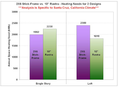
The main conclusion from this analysis is that Stick-Frame and Rastra wall systems perform differently with different home designs. For my single story home design, Rastra walls would require about 15% more heating energy than stick-frame walls to maintain the same interior temperature. However, for my loft design, stick-frame walls would require about 32% more heating energy than Rastra walls. To put these energy needs in perspective, 2 of my PV solar panels will produce the 581 kWh difference between 2X6 stick-frame and 10" Rastra walls for the loft design. Even though the heating energy required for any of these designs is relatively small compared to an average American home, I'm happy to know that my Rastra loft is the best performing design.

The moral of the story is than an energy analysis of your home design can predict your energy needs. The analysis may also help if you are undecided on your wall system. Thanks for reading. As always, your comments are appreciated.